And it’s made with
For my project, I bought one 40cm long 40*20 profile and one 50cm long 20*20 profile.
The laser is mounted on the 20*20, the 40*20 carries the steppersThe hard thing was to tap the threads for the supports. I don’t know if tappingthreads by hand is hard or that’s because I’m a noob but I had hard times to do it. It works but the thread is not perfect. xxx I modeled those supports to print them. To make it simpler I scanned them with my desktop scanner/printer. Pretty handy. Once they were scanned I vectorized them, then extruded. I needed to make them bigger to avoid balancing while the new frame is much bigger.
Here is the STL .
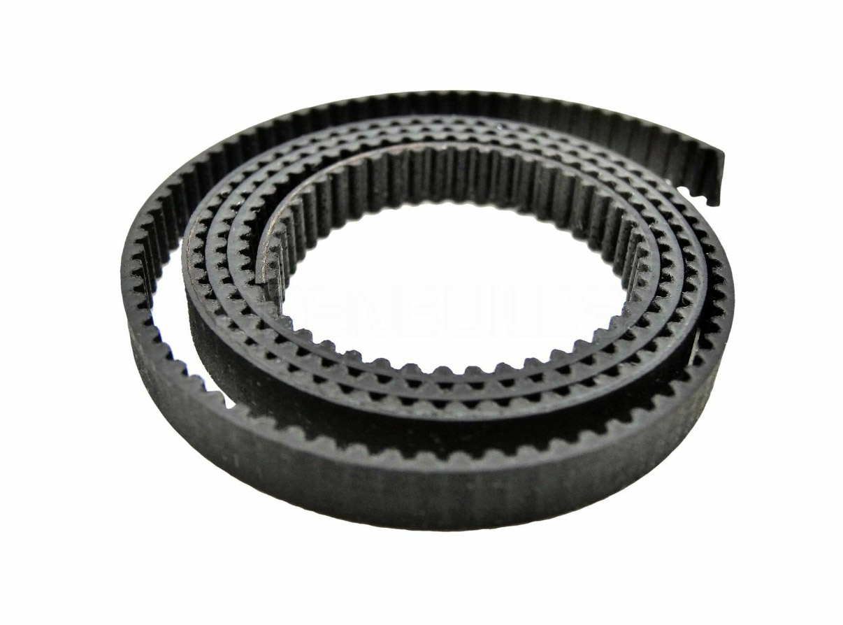
is not much things to say about the cables, you’ll just have to make them longer for them to go to the end. So work on the cables from the main board to the steppers and from the steppers to the laser. Try not to make them too long or they will be stuck everywhere. ave to be careful with the tension of the belt, like 3D printers , it has to be not too tight, not too loose. That said, I still have some issues during the travel, as it goes too fast, It makes a maximum tension and make it stop.
To fix this, you just have to change parameters on GRBL.
So you have to change the values
