Phantom power is often required for proper microphone function. What
is so “phantom” about this powering method and why is it so popular with
microphones? We’ll find out in this article!
What is phantom power? Phantom power is a DC voltage
(typically +48 V) that provides power to the active components within
certain active microphones. This electric power is transmitted through
the same balanced audio cables that carry the audio signal. The term
“phantom” comes from the fact that there is no obvious power cable.
In this complete and in-depth
guide, we’ll unravel the mystery of phantom power and explain everything
you need to know about phantom power and its role with microphones.
As mentioned above, phantom power is a method of providing power to
microphones. It is provided by microphone preamplifiers, mixing
consoles, audio interfaces, and standalone phantom power supplies.
Phantom power travels from the source (at the mic input) to the
microphone through the same cable that sends the mic’s audio signal from
the microphone to the mic input.
There are no dedicated power cables for phantom-powered mics. Rather,
the mic is powered via the same cable that carries the audio signal,
hence the name “phantom power.”
The standard phantom power is +48 Volts DC and this is typically what
you’ll get from professional phantom power sources. However, phantom
power technically ranges from 12-48 volts with various current ratings
between 4 and 22 milliamps.
Phantom power voltage travels through balanced audio cables. More
specifically, it is applied equally to pin-2 and pin-3 with respect to
pin-1 in balanced XLR cables.
To test for phantom power, the voltage measurements between pin-2 and
pin-1, and pin-3 and pin-1 will read identical levels. No voltage is
present between pin-2 and pin-3.
Though +48 V is the standard, other common phantom voltages include:
+12 V DC
+15 V DC
+18 V DC
+24 V DC
+48 V DC
Phantom power is used to power the active components of active
microphones. Generally speaking, it is used to power the impedance
converters and internal preamps of active microphones along with other
active circuits. It is also used to polarize the capsules of condenser
microphones that require external polarization.
Note that not all active microphones run on phantom power. DC bias
and external power supplies are also common, depending on the type of
mic. More on this in the other microphone powering methods section.
It’s also important to note that the modern microphones that do not
require phantom power are designed to essentially ignore it if it is
applied.
Now that we have a surface level understanding of phantom power, let’s look at how it works.
Phantom Power Sources
Phantom power is ultimately produced using electricity from the power
mains or batteries that power the phantom power source. Phantom power
sources include:
Standalone phantom power supply units.
Microphone preamplifiers.
Audio interfaces.
Audio mixing consoles.
The above-listed sources contain active units that convert mains power or battery power into phantom power for microphones.
As discussed, phantom power is typically a +48 volts direct current.
This 48 V DC is designed to pass through balanced audio cables on the
audio lines.
With the typical XLR mic cable, this means phantom power sends +48
volts on pins 2 and 3 (positive and negative audio, respectively)
relative to pin 1 (return).
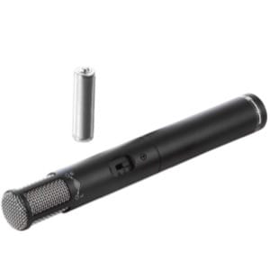
The Rode NT1-A (pictured below) is a phantom-powered condenser microphone with an XLR output:
With TRS (tip-ring-sleeve) audio cables, this means phantom power
sends +48 volts on the tip and ring (positive and negative audio,
respectively) relative to the sleeve (return).
Note that microphones typically receive phantom power through their
connected XLR cable but in some routing situations, phantom power may be
sent through a patch bay (via TRS cables) before reaching the
microphone.
Phantom Power And The Balanced Audio Cable
For simplicity, we’ll discuss phantom power through a common (and
typical) balanced 3-pin XLR cable. XLR cables are wired as follows:
Pin 1: Ground/shield wire
Pin 2: Positive audio signal wire
Pin 3: Negative audio signal wire
3-Pin XLR Female & Male Connections
Basically, the audio from the microphone capsule is sent down pins 2
and 3 (relative to pin 1) of the XLR cable. Audio signals are AC and pin
2 carries a positive polarity mic signal while pin 3 carries a flipped,
negative polarity version of the same signal.
So the audio signals on pins 2 and 3
are completely out-of-phase with each other. At the balanced mic input
(preamp, interface, mixer, etc.), a differential amplifier sums the
difference between pins 2 and 3. This means that the resulting audio
signal is effectively the sum of two in-phase audio signals.
This wiring setup allows for common-mode rejection (CMR). CMR is the cancellation of similar signals on pins 2 and 3.
For example, any noise or electromagnetic interference in the cable
will equally affect pins 2 and 3. Similarly, phantom power applies the
same 48 volts DC on both pins 2 and 3.
What does this have to do with phantom power? Well, since phantom
power is sent through balanced cables, it does not affect the sound of
the audio nor does it add noise to the signal!
So we know that phantom power is a DC voltage on the audio wires of a
balanced cable (pins 2 and 3 of an XLR). This voltage is supplied by a
mic input circuit and travels through the cable to the microphone’s
output connector for use within the mic.
Microphones, whether they require phantom power to function or not,
are designed to effectively take what they need and block what they
don’t need from the supplied phantom power.
For passive microphones, the DC voltage will typically be stopped
just inside the mic’s body. This blocking can be accomplished with an
output transformer as is the case with passive ribbon microphones. It
can also be accomplished with blocking capacitors in the microphone’s
output circuitry.
Moving-coil dynamic microphones sometimes do not have output
transformers. Their capsules, however, will typically not be affected
negatively by phantom power.
Microphones that require phantom power to function properly are
designed with the appropriate circuitry to send phantom power where it
is required. By the same token, the circuitry is designed to block the
DC phantom power voltage from entering circuits where it isn’t needed or
from reaching the components it may damage.
Essentially the mics that need phantom power will accept it and those that do not will ignore it.
With those microphones that need it, phantom power is used for the following functions:
Powering the impedance converter.
Powering the active circuit board components.
Polarizing the externally-polarized capsules.
Though +48 V DC is the standard voltage for phantom power, not all
phantom-powered microphones require the full 48 volts. Some may only
require 9 V DC while others may even require more than the full 48.
Whatever the required voltage is, the microphone will be designed
with appropriate circuits to step-up or step-down the phantom power for
proper powering.
Some lower-end and consumer-grade interfaces, consoles, or other
power supplies will not supply the full 48 volts in an effort to reduce
costs. A lower phantom power voltage may negatively affect the
performance of the microphone.
To find out the true voltage output of a phantom power source, check
the device’s specifications sheet. Alternatively, use a voltmeter to
check the voltage across pins 2 and 1, and pins 3 and 1.
Turning Phantom Power On/Off
Nearly all phantom power sources have switches for turning phantom power on and off.
High-end audio equipment P48 sources (mixing consoles, audio
interfaces, etc.) often offer individual phantom power switches for each
channel. Other sources may have a single switch for all channels or a
few switches that control multiple channels each.
As mentioned above, phantom power originates from the power main.
There are multiple sources that effectively produce phantom power. The 2
main phantom power sources are:
Microphone preamplifiers typically have an included phantom power
circuit with an on/off switch. Because nearly all microphones are
plugged into mic preamplifiers, it makes perfect sense to include a
phantom power circuit in the mic input.
The XLR mic inputs in microphone preamplifiers generally have phantom power circuits.
These mic preamps can be found in all sorts of audio devices including:
Remember that not all microphone preamps will supply the full
standard +48 V DC. Some low-quality preamps will supply slightly less.
Others are even designed specifically to supply a voltage other than +48
V (more on the other phantom power sources later in this article).
There are also standalone phantom power supply units on the market.
These units aren’t so popular since most mic inputs are built with a
phantom power circuit. However, standalone units are required if we want
to plug a phantom-powered mic into an input that does not supply the
correct phantom power (or any phantom power, for that matter).
There are wall-plug and battery-powered standalone phantom power units on the market.
Analog audio and phantom power can both be thought of as electrical circuits.
Microphone circuits range from very simple (with passive dynamic
mics) to incredibly complicated (with some condenser microphones). This
is especially true if we do not understand electrical circuit theory.
On that note, let me preface this by stating that I’m not an expert at electrical circuit theory.
An important safety measure with phantom power is to only switch it
on once the microphone is connected to the source. This will help
prevent electrical shorting and protect the internal circuitry of the
microphone in question.
Note that, with the following 2 basic circuits, we’ll be drawing the diagrams with the standard +48 volts DC phantom power.
Basic Phantom Power – Condenser Microphone Circuit
Here is a simplified diagram of a phantom power source (and the mic
input) to the right supplying phantom power to a condenser microphone
capsule on the left:
Simple Phantom Power – Condenser Microphone Circuit
As we see above, the phantom power
supply, when switched on, passes through equal-value resistors. In the
case of standard +48 V DC, these resistors are both standardized to be
6.8 kΩ and allow for equal power on pins 2 and 3 along with proper
common-mode rejection. These are typically low-noise metal film type
resistors.
As we’ll see in the section on phantom power standards, the value of the resistors isn’t as important as the fact that they match to give exactly the same voltage on both pins.
The capacitors C1 and C2 block the DC phantom power from getting into the mic input differential amplifier stage.
The +48 V DC appears on pins 5 and 8 of the audio transformer. Power for the microphone preamp is pulled off pin 6.
The ground and the negative supply for the preamp comes from pin 1.
The audio output of the preamp appears across the primary of the
transformer.
Since the power is tapped from the center of the transformer, any audio is cancelled and the result is pure DC for the preamp.
Basic Phantom Power – Dynamic Microphone Circuit
Simple Phantom Power – Dynamic Microphone Circuit
The idea here is that there is no flow of current to complete a
circuit path that sends phantom power to the ground. The dynamic element
is isolated from the ground, which means it will not sustain damage
from properly applied phantom power.
Alternatively, dynamic mics will
have an output transformer which will not pass any DC voltage to the mic
element whatsoever. This is true of all ribbon microphones, which have
very sensitive diaphragms.
As we’ll discuss later, these passive microphones can still sustain
damage from phantom power if an electrical short or surge happens.
Active microphones require power to function properly. Many of these
microphones use phantom power but not all. So what types of microphones
require phantom power and which do not?
Mics That Do Not Require Phantom Power
Let’s start by looking at the microphones that do not require phantom power:
Moving-coil dynamic microphones are transducers that work on the
principle of electromagnetic induction. Electromagnetic induction is a
passive electrical process.
There are also no active electrical components (amplifiers, impedance
converters, etc.) in moving-coil dynamic microphones that require
phantom power to operate.
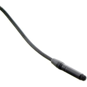
DC-biased electret microphones, like the majority of miniature
lavalier microphones, are certainly active but do not require phantom
power.
Rather, these mics work on a DC-bias voltage. These mics are
generally designed with unbalanced mic cables and are powered with a
DC-biasing voltage (which is typically 5 volts DC instead of phantom
power’s 48 volts DC).
Tube microphones are also active microphones but require more power
than phantom power can provide. Tube microphones require external power
supply units to properly power their active components (tubes and
capsules).
Electret FET microphones include the DC-biased microphones mentioned
above. However, many electret mics require phantom power to function
properly.
These electret mics are generally studio-type microphones but range from consumer to professional-grade.
Electret condenser microphone capsules are built with electret
material in their design and are quasi-permanently charged. The electret
(a portamento between electric and magnet) material maintains a
permanent charge across the condenser capsule.
Therefore, external power (like phantom power) is not needed to polarize the capsule of electret microphones.
Instead, phantom power is used to properly power the impedance
converters (FETs) and, sometimes, the other active electrical components
in the electret microphone’s circuitry.
True FET condenser microphones nearly all require phantom power. True
condenser microphones, for the most part, are studio-grade microphones
and so phantom powering should be readily available in more situations
where a true condenser is used.
Like the electret microphone, true condensers require phantom power
to properly power their impedance converters (FETs) and their other
active electrical components.
Unlike electret capsules, true condenser microphone capsules require
an external polarizing voltage. This voltage is supplied by phantom
power as well.
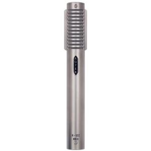
Active ribbon mics are passive transducers since they still convert sound to audio via electromagnetic induction.
However, the low-level mic signal
from the ribbon element is processed and amplified by active components
before the audio signal is outputted from the microphone.
These active components (impedance converters, amplifiers, etc.) generally require phantom power to function properly.
Recap On Microphone Types And Phantom Power
To recap, let’s look at a table to quickly layout which mic types need phantom power and which do not:
Phantom power is standardized under the International
Electrotechnical Commission Standards Committee (IEC)’s IEC 61938:2018.
This document is otherwise known as “Multimedia Systems – Guide To The
Recommended Characteristics Of Analogue Interfaces To Achieve
Interoperability.”
The IEC 61938 defines 3 different voltage levels for phantom power:
P12 (12-volt DC).
P24 (24-volt DC).
P48 (48-volt DC, which is the professional standard).
Phantom power is a positive voltage applied to both signal
conductors of a balanced cable. Both conductors are fed through
resistors of equal value:
680 Ω for 12 V
1.2 kΩ for 24 V
6.81 kΩ for 48 V
This symmetry in circuitry is to maintain good common-mode
rejection in the mic input circuit’s differential amplifier. The matched
resistors must be matched within 0.1% of each other.
Two specialized variants of phantom power have been developed for specialized applications:
P12L (low-power applications).
SP48 (super-power applications).
Let’s look at the specifications of each of the 5 phantom power standard as defined by IEC 61938 (source):
Phantom Power Standard
Voltage
Current (Max)
Current (Rated)
Matching Resistors
P12L
(low-power applications)
12 V +/- 1 V
8 mA
4 mA
3300-ohm feed resistors
P12
12 V +/- 1 V
15 mA
15 mA
680-ohm feed resistors
P24
24 V +/- 4 V
10 mA
10 mA
1200-ohm feed resistors
P48
(standard)
48 V +/- 4 V
10 mA
7 mA
6800-ohm feed resistors
SP48
(super power applications)
48 V +/- 4 V
22 mA
22 mA
2200 ohm feed resistors
It’s important to note that lower-quality phantom power supplies may not supply the full standard voltage(s).
Although the vast majority of phantom power supplies send P48 through
balanced XLR connections/cables, P48 does not necessarily require XLR
to function properly.
So long as the cable is balanced, it will be able to pass phantom power.
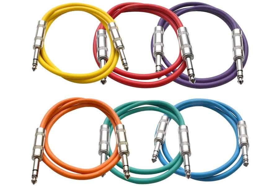
A common example of a balanced non-XLR cable that passes phantom power is the typical TRS cable used in a studio patch bay.
Patch Bay
1/4″ TRS “patch” cables much smaller than XLR cables and are easier
to patch with. Not only do they connect and disconnect more easily, but
their size allows for more patching pathways in a smaller patch bay
unit.
The TRS connector is analogous to the XLR connector in the following ways:
These TRS patch cables do not
generally plug directly into a phantom power source or directly into a
microphone. Rather, the patch cables are used in routing setups and will
pass audio and phantom power from one point to another.
That being said, there is a big reason why phantom power sources
utilize XLR rather than TRS. This reason is electrical shorting (or the
lack thereof).
XLR cables are designed with 3 pins. The audio pins 2 and 3 are equal
lengths while the ground pin 1 is slightly longer. This means that when
an XLR connector is connected, it is grounded before the audio (and
phantom power) circuit is completed. Because pins 2 and 3 are equal
lengths, they are connected at the same time and no shorting occurs.
TRS connections, on the other hand, are designed sequentially.
So when connecting a TRS plug into a TRS jack, the tip of the plug
first hits the sleeve, then the ring, then the tip of jack. The ring of
the plug follows, hitting the sleeve before connecting to the ring of
the jack. Once the TRS is completely plugged in, the TRS of the jack
fully connects to the TRS of the plug.
However, when physically connecting or disconnecting these TRS jacks,
we cause electrical shorts (when tip connects to ring, for example).
These shorts may very well cause improper flow of phantom power which
can harm the microphone.
For this reason, “hot patching” (plugging-in and unplugging patch cables) is not advised while phantom power is engaged.
To recap, XLR connections to do not short and are much safer than TRS cable when it comes to carrying phantom power.
Generally speaking, phantom power isn’t dangerous. I’ve never heard
of phantom power causing bodily harm to anyone, for example. However, it
is possible for phantom power to damage microphones.
It is important to know how phantom power may negatively affect microphones so we are better equipped to use P48.
For example, some multi-channel mic preamps can only apply phantom
power across multiple channels rather than on a per-channel basis.
Knowing whether a microphone can handle phantom power or not is
essential in these situations.
The situations that could potentially cause phantom power to damage a microphone include:
Electrical shorting, which was previously mentioned, will momentarily
send the phantom power voltage up one audio conductor rather than both.
Even an instant of electrical shorting can cause the DC voltage to
enter the wrong parts of the microphone and damage the mic.
Phantom Power Damage Through Power Surging
Power surges can overload the phantom power circuit. The spike in
electrical current can fry certain wires or components within the
circuit.
Power conditioners are always advised in the studio or any other
situation where expensive microphones and audio equipment are being
used.
Phantom Power Damage To Unbalanced Microphones
Phantom power requires a balanced connection to work properly. If
phantom power is forced through an unbalanced cable to an unbalanced
microphone, the 48 volts on the audio cable may very well overload the
microphone and cause serious damage.
Unbalanced microphone examples include many karaoke microphones and
even many of the professional DC-biased lavalier mics on the market.
Will Phantom Power Hurt A Mic That Doesn’t Need It?
Most microphones have balanced outputs with the appropriate output
circuitry to either accept phantom power or, in the case the mic doesn’t
need phantom power, effectively stop it from entering the mic’s
circuitry.
One such example of this is the output-coupled transformer which only
passes AC voltage (the mic signal). Having a transformer at the output
of the microphone will protect it from proper phantom power.
Some dynamic microphones are transformerless but can handle having phantom power enter their passive circuitry.
So most professional-grade microphones that have balanced outputs will not be damaged by proper phantom power.
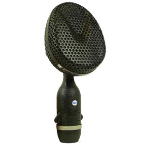
One common concern with ribbon microphones is the potential for
phantom power to destroy the fragile ribbon diaphragm. Passive ribbon
microphones, therefore, are designed with output transformers to protect
them from DC voltage.
The microphones that would likely get damaged by phantom power, even
if it was applied correctly, are the unbalanced microphones. Think
belt-pack lavalier microphones and karaoke mics.
Fortunately, these microphones do not have XLR connectors, so it
would require some effort (and adapters) to even apply phantom power to
the microphones in the first place.
Will Phantom Power Damage Wireless Receivers?
Like professional microphones, the majority of wireless microphone
receivers have balanced outputs. These output circuits will typically
have the necessary phantom power blockers in order to keep the receivers
safe.
There are some microphones on the market that offer the option between powering the mic with batteries or with phantom power.
It is advised, with these microphones, that we remove the internal
batteries when phantom powering is used to avoid the potential corrosion
and leakage of the batteries.
In these cases, phantom power may be dangerous in affecting the batteries, though this isn’t a major concern.
History Of Phantom Power And The First Phantom Powered Microphone
Phantom power came about in the 1960s when mic manufacturers began
using transistors instead of vacuum tubes in their condenser
microphones.
Phantom power came about as a method of powering these solid-state
mics via the same cable that carries the mic audio rather than with an
external power supply (like tube microphones).
The vacuum tube was invented in 1904 by Sir John Ambrose Fleming.
In 1905, Lee De Forest invented the first triode vacuum tube (the
basic tube used in microphones). The triode vacuum tube patent was
awarded in 1906.
It wasn’t until 1928 that the first-ever tube condenser microphone
was released to the market. This microphone was the Neumann CMV3 (better
known as “the bottle”).
Neumann CMV3
Tube microphones, by their design, require a lot of power in order to
properly polarize their capsules and heat their vacuum tubes. This
power is supplied by external power supply units that plug into the
wall.
In 1947, Bell Labs made a huge advance in the technological world with its new invention: the transistor.
Transistors could effectively fill the role of vacuum tubes with the
added advantages of being smaller in size and requiring less power to
function properly.
In typical audio technology fashion, it took some time before the
first-ever transistor-based microphone. In 1965, Schoeps produced the
CMT20, the world’s first solid-state microphone. In 1966, Neumann
produced the CMV3, the world’s first phantom-powered microphone.
What we know as “microphone phantom power” today originated in the
NRK (Norwegian Broadcasting Corporation). Because of the limited
daylight in the winter months in Norway, their studios were equipped
with auxiliary lighting, which was fed by a +48 volts DC power supply.
In the 1960s, microphone manufacturers began introducing transistor
technology into their microphones. Neumann GmbH, eager to bring their
new solid-state microphones to Norway, visited the NRK in 1966.
Neumann’s new solid-state microphones required less power than the
tube microphones that preceded solid-state mics on the market. There was
potential to power these microphones without an external power supply
but rather through the same cable that carried the audio signal.
And so it was settled that Neumann would design their microphones to
run on the +48 volts DC power supply provided by NRK studios. This DC
voltage would run on pins 2 and 3 of a 3-pin XLR connector.
Since then, +48 V DC has become the standard (in DIN 45596) for microphone phantom power.
The First Phantom Powered Microphone
Although Schoeps produced the first
solid-state microphone with a transistor in 1965 (the Schoeps CMT 20),
it was Neumann that produced the first-ever phantom-powered microphone.
This microphone is none other than the legendary Neumann KM 84.
Neumann KM 84
The KM 84 (now discontinued) was a small-diaphragm pencil condenser
microphone with an externally polarized capsule and a cardioid polar
pattern.
Phantom power effectively polarized the capsule of the KM 84 and
powered its active FET circuitry. This microphone used an output
transformer.
Before we get into the other microphone powering methods, let’s discuss digital phantom power.
The Audio Engineering Society (AES) published a set of standards
called the AES 42 that specifies 10 volts DC of phantom power for
digital microphones.
Digital mics that comply with the AES 42 standard will run on this 10
V DC phantom power. The current of digital phantom power can be as much
as 250 mA.
Digital phantom power is delivered in very much the same way as
regular phantom power though the vast majority of analog P48 sources do
not supply digital P10. Rather, digital phantom power supplies send
their power via XLR or XLD connectors.
XLD is a simply a keyed variant of the XLR cable with the same wiring
but a different groove for connection that helps to prevent interchange
of analog and digital devices.
It’s important to know that phantom
powering is not the only way to get power to active microphones. In
fact, there are many other methods to send power to the microphones that
require it.
Bias is a DC voltage generally between 1.5 – 9 volts that travels on a single audio conductor.
Therefore, DC-Biasing is a popular powering method for miniature
unbalanced lavalier microphones and is often supplied by wireless
lavalier transmitters.
Because of the low voltages of DC-bias supplies, this powering method
is mostly reserved to power the JFETs of miniature electret lav mics.
With these microphones, it is only the impedance converter that requires
powering and a small DC-bias voltage is enough to power them correctly.
T-Power (A-B Powering)
T-Power (T12) is a Deutsches Institut für Normung (German Institute for Standardization) standard written in DIN 45595.
It was one of the first methods to power condenser microphones
through their audio cables. Phantom power, however, has effectively
replaced T-power as the standard microphone powering technique.
With T-power, 12 volts DC is applied through 180Ω resistors between
the positive audio wire (pin 2) and the negative audio wire (pin 3).
These 12 volts of potential difference across pins 2 and 3 could lead to
high current across these pins which would likely cause permanent
damage to dynamic and ribbon mics. It’s no wonder the safer phantom
power method has replaced T-power.
Plug-In-Power
Plug-in-power (PiP) is covered by Japanese standard CP-1203A:2007 and the IEC 61938.
Plug-in-power is used to power consumer-grade electret microphones
that connect to consumer audio equipment such as portable recorders and
computer sound cards.
It is a low-current source that supplies +5 volts DC. This method
sends power through an unbalanced cable, using the sleeve/shield as a
return.
PiP works similarly to DC-biasing in the fact that it works on an
unbalanced line and is typically used only to power the impedance
converters of microphones with low power requirements.
External Power Supply Units
For microphones that require more
power than phantom power can provide, an external power supply unit is
likely necessary. This is true of practically all the tube microphones.
Vacuum tubes essentially provide the same function as FETs. That is,
they both act as impedance converters and pseudo-amplifiers for the
microphone signal.
A major difference, though, is the amount of power they each require.
While microphone transistors can work with phantom power, mic tubes
require much more power and, therefore, an external power supply unit
that is capable of supplying this power.
Some microphones are battery-powered. Oftentimes these mics will have
an option to power the microphone directly with one of the
above-mentioned techniques.
Can you use a condenser mic without phantom power? Though all
condensers are active, many condenser mics are designed to function
with powering methods other than phantom power. These powering methods
include DC-biasing, external power supplies, T-power, and batteries.
What is the difference between a condenser mic and a dynamic mic?
The main difference between condenser and dynamic microphones is the
transducer element. Condenser mics have active capsules that work on
electrostatic principles while dynamic mics have passive capsules that
work on electromagnetic induction.
Arthur is the owner of Fox Media Tech and author of My New
Microphone. He's an audio engineer by trade and works on contract in his
home country of Canada. When not blogging on MNM, he's likely hiking
outdoors and blogging at Hikers' Movement (hikersmovement.com) or composing music for media. Check out his Pond5 and AudioJungle accounts.
Even the best audio equipment can perform deficiently if the
audio connections are made improperly. A dirty headphone or aux jack can
lead to popping and crackling, intermittent signal flow, and even...
A studio monitor and a bookshelf speaker may share similar form
factors and aesthetics, but do they serve the same purpose?
Furthermore, can you use them for both endeavours?
What are the...